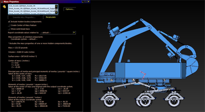
This article is the "Requirement gathering & Analysis" phase of the SDLC (several iterations around), which evaluates the current state of the Curivator. For reference see pictures
What can be observed from these pictures is two areas of concern for unwanted deflection:
One thing to add in regards to the weak bridge joints is when I had experienced a fall (see picture). Let's lay out the SDLC phases and how they relate:
These phases, go back around in a circle, and we keep iterating while the robot continues to improve from where it was before.
Let's take a look at the load:

The robot weighs approximately 180 pounds and 120 pounds all rests upon 2 rocker bridge joints. This is easy to see from front view, so there is a bending moment, and while the distance between the uniform load, and fixed point is less than .75" (I was hoping this could suffice) the actual tilting of the rockers suggest that it is deflecting. I'll want to isolate the shaft and either run the beam calculator on it (TODO), or the simulation.
Prior to this bending moment the front end lowers perhaps as much as 3 inches, making the robot look like a drag racer, the crumpled rocker (especially the port side) gives deflection on the fold and starts to flatten out the angle. I'll want to see if I can reproduce how much deflection occurs on the simulation, but may need to factor out the fold to accomplish.
TODO: Run simulations before starting this
I believe the solution may be to use .125" thick rockers that use machined precision etch and brake technique. I'm still not certain if a gradual fold is stronger than a precision fold, but given the new thickness it makes sense to use a brake for easier implementation. We'll want to preserve the geometry to conform to the existing prints to minimize work. Since these parts are created and then folded (i.e. parts created in Solidworks in this regard), it should be simple to manipulate the thickness. This will require .07" more shaft which should be fine, we'll be able to see in the CAD all the changes.
If it turns out the shafts need to be strengthened, we can simply modify the shaft's material properties (e.g. steel).
To implement the new rockers, I could do so by printing out the drawing and using a bandsaw, but for the sake of getting more practice on the CNC machine we'll mill it, using etching for the folds. Also I may want to give MasterCam a try here.
Once parts are made, it is easy to install I'll test one side first and we can compare one side to another in doing so.
I'll wish to take a baseline measurement of old rockers (TODO put here). Compare this against the new rockers, and compare against the CAD.
We'll also want to drive the robot to put more stress on the joints. I'm a bit worried of pulling forces that may occur from the center wheels if they try pull away from each other. If this happens, can the joints be strong enough to withstand? (that may be something to watch closely in the next iteration).
I'll continue to use the stands to avoid material fatigue, unless there is no evidence of this happening. Ideally I would like to have it strong enough to not need them. Also will to need to continue visually inspecting surrounding parts and keeping the tires aired periodically.